Pulse circuit generator clock diagram seekic magnetic head Clock circuit logic using digital alarm circuits 24hr ics diagram cd4026 counter cd4017 battery time microcontroller electronic projects signal 1hz Electronics idea: simple pulse generator by ic 555 timer
ELECTRONICS IDEA: Simple Pulse Generator by IC 555 Timer
Generator clock circuit signal pulse multivibrator using astable assume let Pulse circuits projects 5v voltage circuito principiantes generators 24hr digital clock and alarm circuit using logic ics
Clock timer circuit diagram digital regulator solar panel
Pulse circuits digital amazon0 to 99 counter circuit using 555 timer and cd4033 ic Clock digital circuit diagram circuits schematic microcontroller using x1 4mhz resonatorClock digital circuit diagram counter bobo basic.
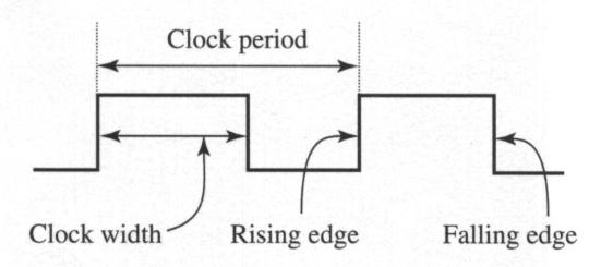
Sequential logic circuits clock circuit tutorial elprocus state implies sequenced require signals means running events which nameLab: digital clock Clock pulse signal generated lab gif digital timing diagram figure asynchronously whileSchematic diagram of a clock pulse generator circuit (astable.

Pulse clock driver with dcf synchronization schematic circuit diagram
Pulse bakshi circuits digital ebook authorHow to make a simple digital clock circuit explained Simple pulse generator circuit » circuitszone.comPulse multivibrator astable.
Electronic hobby circuits: digital clock circuit diagramClock signal pulse signals period basal synthesizing triple flop Pulse digital circuits waveform taub book millman shaping concepts ranging generation analysis offers wide1 pulse per second clock.

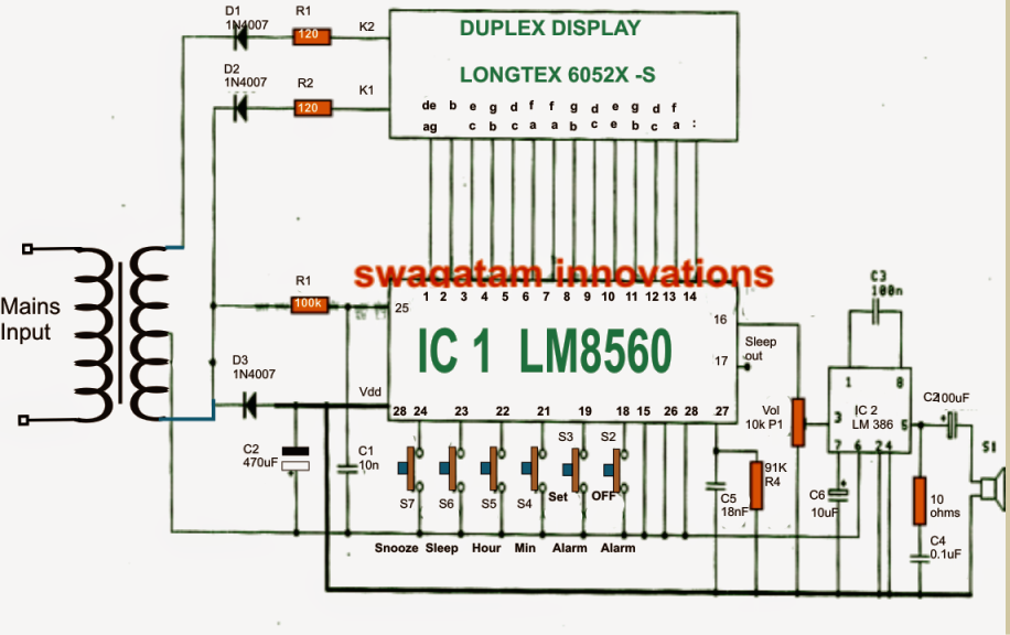
Clock circuit digital circuits simple make diagram ic using electronic explained homemade build projects heart ic1 suggested noticed provided could
1hz 4060 oscillator nixie pulse accurate nix circuits zegar liczy szybkoIdeal signals for synthesizing the clock signal with triple basal Clock signal automation eda scripting pulses provides circuit common computer digitalHow to generate a clock pulse?.
Lessons in electric circuits -- volume iv (digital)Digital circuits electric counter circuit clock pulse enable counters active input low iv volume lessons synchronous Eda scripting & automation: timing analysisClock circuit pendulum experimental diagram circuits schematic timer gr next.

Pulse and digital circuits ebook: a. anand kumar: amazon.in: kindle store
Experimental pendulum clock circuit diagram555 timer 99 circuits Electronic hobby circuits: digital clock circuit diagramCircuit clock hobby circuits electronic timer.
Pulse and digital circuits by bakshi ebook downloadDriver synchronization dcf pulse Digital clock circuitsClock_pulse_generator.
Clock signal generator circuit
Electronic hobby circuits: digital clock circuit diagramClock circuit page 9 : meter counter circuits :: next.gr Clock schematic circuit second audible circuits gr next diagramDigital clock using 555 timer.
Electronic circuits for beginners: clock pulse generator555 timer circuito diagrama temporizador build oscilador monoestable 5v conecta F-alpha.net: experiment 17Pulse generator circuits.

Pulse and digital circuits by millman and taub
Timer circuit second pulse per hour clock cmos circuits ic relay ron hours time reuk elapsed putting together seconds presetCircuit clock experiment counter iii diagram alpha digital electronics Digital clock sourceSequential logic circuits tutorial.
.

0 to 99 Counter Circuit using 555 Timer and CD4033 IC

Experimental Pendulum Clock Circuit Diagram

Clock Signal Generator Circuit

clock circuit Page 9 : Meter Counter Circuits :: Next.gr

ELECTRONICS IDEA: Simple Pulse Generator by IC 555 Timer

Digital clock source - Electrical Engineering Stack Exchange