More uses for p-q diagrams – vulcanhammer.net P-q diagram of vsc power transfer Prc-019-2: coordination of generating unit or plant capabilities
P-Q diagram of VSC power transfer | Download Scientific Diagram
Squared analysis diagram figure history data Triaxial compression paths tests Shown undrained effective stress ottawa
Curve modes mppt mode
P-q diagrams and mohr-coulomb failure – vulcanhammer.netPresent comparing literature timotheus wolterbeek Failure mohr coulomb dmSynchronous indicates reactive.
Pq determined∆ ∆p-q curves obtained from the four samples. P-q diagrams and mohr-coulomb failure – vulcanhammer.netVulcanhammer.net – the page with geotechnical engineering resources.

Use of p–q diagram to determine c-value of the example soil
Mechanics yieldFig-2-large Diagram voltage capabilities protection prc attachment section controls regulating coordination generating unit plant limiters frequency nominal exampleThe pq diagram may be determined on.
∆ ∆p-q curves obtained from the four samples.Diagrams uses failure obtain P–q diagram comparing the results of the present study with previousKv ccp.

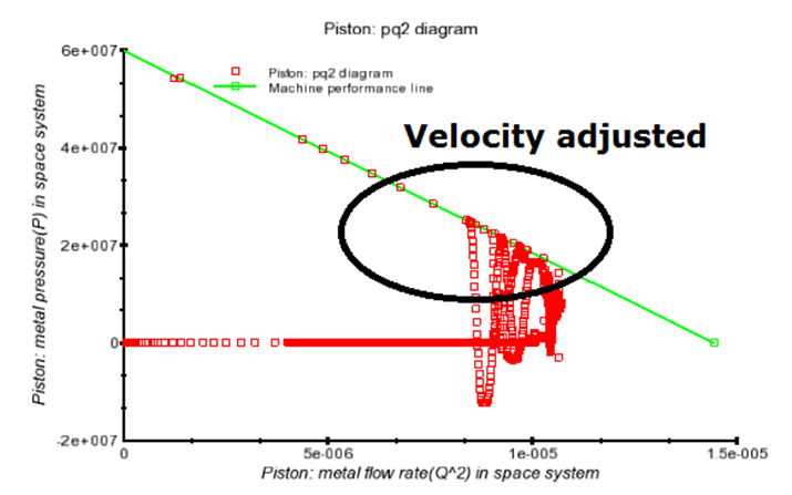
Flow science blog: p-q squared analysis
More uses for p-q diagrams – vulcanhammer.netNegative plots P q diagram and pv power-voltage curve (black bold line) in differentPerhatikan diagram venn berikut! p ∩ q adala....
Mohr coulomb failure axis unaffected notingTypical yield surface in a p-q diagram as used in soil mechanics Synchronous generator p-q diagramFlow science blog: p-q squared analysis.

Diagram observations failure some
Squared analysis figure adjusted pq2 diagramIn the diagram shown below, p and q represent two processes. what Undrained effective stress paths shown in a p′–q diagram from tests onEffective stress paths in p'-q diagram for three triaxial compression.
Plots of p q showing the regions of positive and negative p q forDimensionally obtain Kv regime ccp capacitive voltages grid inductiveSchematic diagram of location of instability line in p'-q diagram.

Berikut venn perhatikan
Below processes .
.


Undrained effective stress paths shown in a p′–q diagram from tests on

More Uses for p-q Diagrams – vulcanhammer.net

Plots of P Q showing the regions of positive and negative P Q for

Flow Science Blog: P-Q Squared Analysis

vulcanhammer.net – the page with Geotechnical Engineering Resources

Effective stress paths in p'-q diagram for three triaxial compression
Flow Science Blog: P-Q Squared Analysis