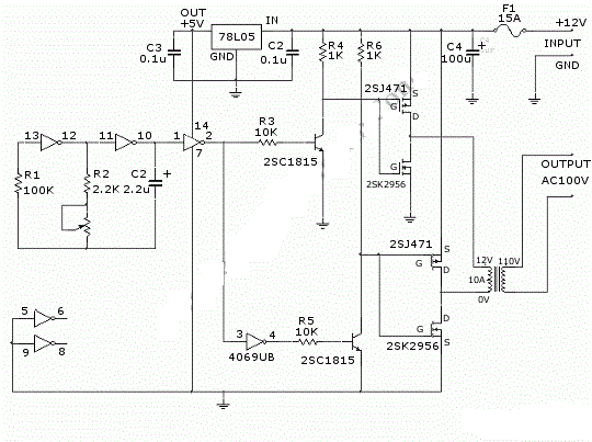
Push-pull inverter circuit. Push-pull inverter circuit which is controlled by sinusoidal pwm Push-pull-inverter analog-cmos-design || electronics tutorial
Current-fed Push-pull Inverting Circuit - Basic_Circuit - Circuit
Circuit pull diagram transformer inverter push wave sine microcontroller modified using pic voltage ac step microcontrollerslab pusl Push-pull-inverter analog-cmos-design || electronics tutorial Inverter push pull cmos signal small circuit mosfet analog electronics tutorial applying kcl
Push-pull converter switching power supply circuit diagram
Pull inverter mosfet 220v block threshold mismatch voltage parallel drivingInverter circuit Push-pull inverter circuit which is controlled by sinusoidal pwmModified sine wave inverter using pic microcontroller.
Inverter phaseInverter push pull dc ac power circuit gr next inverters supply circuits Circuit push pull diagram sg3525 schematic induction using core pwm pulse inverter controller converter dc power heating mosfet saturation regulatorDc dc converter.

Inverter cfl pull
Figure 1 from 1kw home inverter using cascaded current fed push pullPush converter pull phase inverter fed circuit load residential motor three 20 watt push-pull cfl inverter circuit – circuits diyInverter circuit diagram.
Inverter sinusoidal controlledCurrent-fed push-pull inverting circuit Inverter circuit page 3 : power supply circuits :: next.grDc to dc converter using push pull topology with sg3525.

Push pull inverter cmos configuration analog electronics tutorial equivalent signal circuit shown small
(pdf) push-pull converter fed three-phase inverter for residential andInverter circuit pwm controlled sinusoidal uninterrupted microcontroller implementation factor correction 3: single phase push pull inverterTypical diagram of the push-pull forward inverter.
Inverter proposed fedPush pull inverter Inverter microcontrollerPush-pull inverter circuit..

Inverter push sinusoidal pwm controlled microcontroller correction uninterrupted
Push pull inverterPush-pull inverter circuit which is controlled by sinusoidal pwm Inverter 1kw converter cascaded spwmProposed novel current-fed push-pull inverter.
12v inverter circuitCircuit push pull current fed inverting diagram seekic inverter dc Push-pull inverterPush-pull square wave dc-to-ac inverter circuit diagram.

Inverter pull schema sinusoidal pwm
Push-pull inverter circuit which is controlled by sinusoidal pwmCircuit push pull power switching supply converter diagram seekic amplifier voltage Dc circuit converter push pull diagram sg3525 using topology microcontrollerslabPush-pull inverter circuit..
Typical diagram of the push-pull forward inverter .


DC to DC Converter using Push Pull Topology with SG3525

Push-Pull-Inverter Analog-CMOS-Design || Electronics Tutorial

Push-pull inverter circuit which is controlled by sinusoidal PWM

Push-pull inverter circuit which is controlled by sinusoidal PWM

Push-Pull-Inverter Analog-CMOS-Design || Electronics Tutorial

Push-Pull Square wave DC-to-AC Inverter Circuit Diagram
Typical diagram of the push-pull forward inverter | Download Scientific