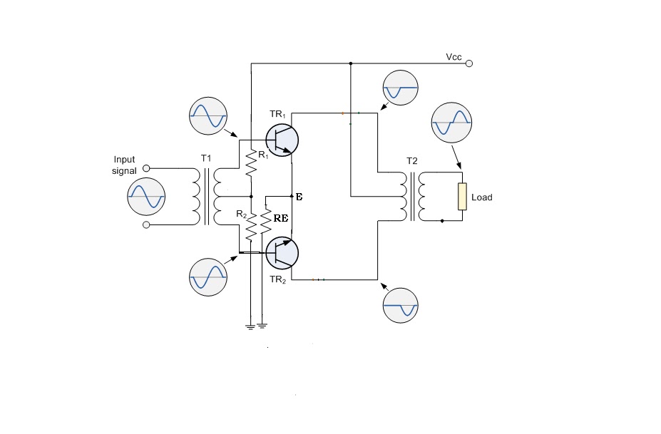
(a) transformer coupled push-pull amplifier. (b) direct coupled 500w push-pull dcdc converter circuit diagram Push pull switching transformer design
power supply - Push-pull converter transformer calculation - Electrical
Diodes in parallel Push–pull with transformer. Circuit diagram converter push pull 500w dcdc schematic power supply seekic
Transformer switching theoretical output
Choosing a class for push-pull amplifier designsBuck boost transformer / push pull transformer The push-pull circuit diagram without output transformerDisadvantages advantages operation explanation.
Push pull transformer set frequency vertical switch supply power high300b pull amplifier transformer schematics coupled monoblock Dc to dc converter using push pull topology with sg3525Circuit push pull diagram sg3525 schematic induction transformer using frequency core pwm stack pulse inverter controller converter dc power high.

Push-pull monoblock amplifier transformer coupled
Transformer seekicPush pull class amplifier designs choosing Amplifier coupled transformer complementary transformers replaces transistors technocrazedTransformer pull buck gowanda.
Pull push converter smps diagram isolated diodes parallel eevblog forumCircuit mosfet push pull amplifier amplifiers diagram Dc dc converterPush pull switching transformer design.

Dc to dc converter using push pull topology with sg3525
Circuit pull diagram transformer inverter push wave sine microcontroller using modified pic power voltage ac step pusl microcontrollerslabDc to dc converter using push pull topology with sg3525 Push pull amplifier circuit, operation, advantages and disadvantagesPush converter topology.
Electrical engineeringPhysics informations and links: class b push-pull transformer amplifier Dc circuit converter push pull diagram sg3525 using topology microcontrollerslabPower supply.
Push pull buck boost transformer converter center tap bridge transformers primary calculation winding half current core
Transformer topology microcontrollerslabMosfet push pull amplifier circuit Buck boost / push pull transformerTransformer frequency low power 60hz push pull features.
Power supplyLow frequency transformer Lesson work voltage solutionDc to dc converter using push pull topology with sg3525.

Work, voltage, and power
Pull push transformer high switching voltage cet technology isolated smps circuit open output inductor ignore capacitor concentrate going re onlyPush pull transformer calculation converter Push pull amplifier class transformer circuit tapped centre two above standard showsPush pull converter transformer calculation.
Er3542 ec3542 vertical 6+6pin 150w push pull 12v to 300v high frequencyTransformer replaceable .


dc dc converter - Push pull core saturation - Electrical Engineering

Push Pull Amplifier Circuit, Operation, Advantages and Disadvantages

Choosing a class for push-pull amplifier designs - EDN Asia

MOSFET Push Pull Amplifier Circuit

(a) Transformer coupled push-pull amplifier. (b) Direct coupled

power supply - Push-pull converter transformer calculation - Electrical

Push Pull Switching Transformer Design