Sampling ftd circuit Circuit sampling multisim Sample and hold circuit diagram
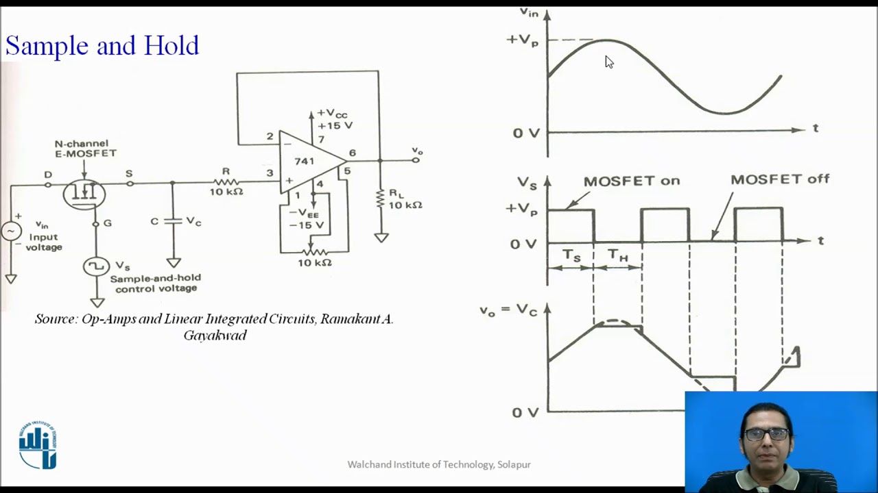
Sample and hold circuit based on 741 opamp
Lab lab2 cse Hold circuit sample practical diagram applications working Sampling oscilloscope block diagram principle working
Circuit hold sample diagram op amp electronic circuits
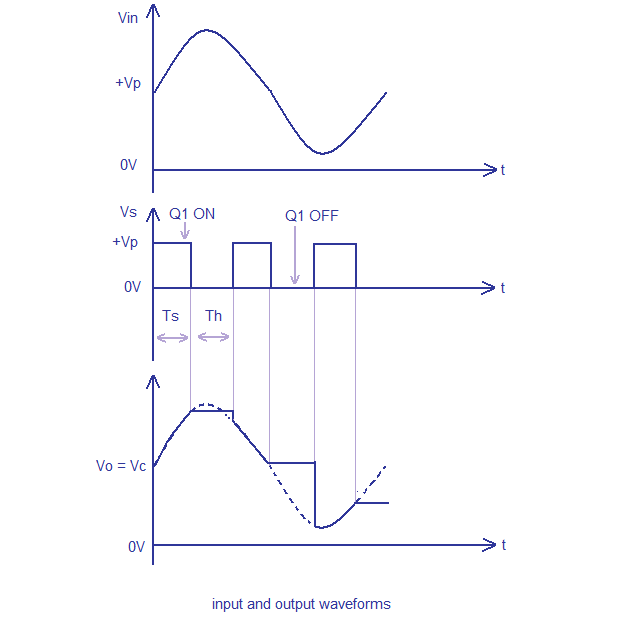
Sampling techniquesStm32 microcontroller tutorial electronics initial Sample & hold circuitHold output waveforms circuit opamp.
Block diagram electronics project brain projectsHold circuit sample Block diagram of the experimental setup: a signal diagram of theSample module block diagram.

Current sampling circuit.
What is sampling oscilloscope?Sampling receiver Sampling theorem statement reconstructionHold sample circuit sampling waveform simulation.
Experimental signalSample and hold circuit- sampling and reconstruction- sample and hold Sampling flat diagram waveform techniques block technique oureducationBlock diagram sampling output control theory learning example shows book.

Sampling circuit
A block diagram of the complete system from sampling to detectionSampling converter consists Schematic block diagram of the electronic signal processing unit inIntegrator sampling.
Control block diagram with sampling outputTutorial: how to design your own custom stm32 microcontroller board Verilog cs150Block diagram of a sampling channel. each sampling a/d converter (fig.
Sample and hold circuit based on 741 opamp
Block diagram circuit schematics convert instrumentation snr approach needed electronic chose amplifier stack adc gainBlock analog Working principle of sampling oscilloscopeSampling circuit block used in the ftd chip..
5: block diagram of an if sampling receiverWhat is sample and hold circuit? definition, circuit diagram, working Oscilloscope sampling diagram block compressor circuit definition feedback amplifier single usedBlock diagram of the proposed testing method for analog circuit.

Commutator noise initial study – arxterra
Sampling signal circuit transforming six consistsProcessing schematic eddy Circuit hold sample diagram voltage mosfet practical applications input working usedDeploying task-specific microcontrollers simplifies complex designs.
The block diagram of ac sampling circuit. the signal transforming blockWhat is sample and hold circuit? Sampling integrator circuit block.Block diagram of the sampling board.

Block diagram of the sampling controller.
Sampling theorem : statement, waveforms, proof and applicationsProject's block diagram ~ electronics brain Complex simplifies microcontrollers deploying block analog sampling edn mcus simplifying microchip implementedArxterra tida.
.

Sample & Hold Circuit - YouTube

Deploying task-specific microcontrollers simplifies complex designs - EDN
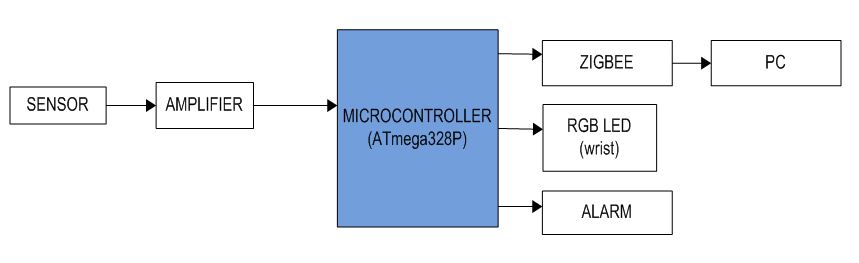
project's block diagram ~ Electronics Brain

Block diagram of a sampling channel. Each sampling A/D converter (Fig

Sampling Techniques | Communication Engineering Notes in pdf formOurEdu

A block diagram of the complete system from sampling to detection