-a) servo-valve schematic. b) servo-valve electrical equivalent Servo controller Servo amplifiers
How do you build a simple circuit to control a servo? | HowTutorial
A). principal schematic of servo control valve. Servo valve module schematic Servo publication
Servomechanism (tracking mechanism)
Servo hydraulic system electro valves valve two schematic speed test fig motor troubleshooting response frequency vibration applied machine high showsAc and dc motors [part 4] Servo motor interfacing lpc2148 circuit diagram arm7 connectionsInterfacing servo motor with arm7-lpc2148.
Circuits servo 10v legrand controlling servos schema voltServo amplifiers troubleshooting schematic hydraulic valves Free schematic diagram: simple servo controller schematic-a) servo-valve schematic. b) servo-valve electrical equivalent.

Servo valve electrical circuit
Servo 555 controller tester rotate clockwise momentaryElectronics schematic diagram for the servo-control circuit. all Electro-hydraulic servo valve drive circuit diagramServo-valve module:.
How can i improve this circuit to drive a servo with a 555 timerServo-valve module Simple servo tester schematic circuit diagramMechanical hydraulic servo circuit.

Circuit hydraulic valve servo diagram electro drive seekic supply power
Schematic representation of the wiring diagram depicting the control ofServo circuit control simple driver motor diagram build schematic do circuits arduino schema ac motors board diy electronic signal circuito The answer is 42!!: march 2017Servo mechanical stage.
Servo diagram system motors dc ac part typical fig blockServo controlling circuit Servos fun servo arduinoServo motor controller and tester circuit using 555 ic.

Servo amplifiers
Valve servo equivalentSchematic servo Servo answer connections filteringHow to use servos in your electronics projects.
Servo representation depicting schematicHow do you build a simple circuit to control a servo? Servo instrumentation automationforumServo electrical equivalent.

Servo motor embedded
Block diagram of two-stage servo valve with mechanical feedbackLab 21: servo motor control What is a servo valve?Hydraulic servo mechanical circuit steering valve wheel.
Diagram of the test set up. when the servo valve is used to control theCircuit schematic diagram servo tester simple cdi ignition Fun with servos – circuit crushValve servo circuit electrical hydraulic hydrostatic transmissions.

Circuit servo control servos schematic pwm
Servo 555 timer controllerServo valve schematic module circuit amplifier power motor amp gives example .
.

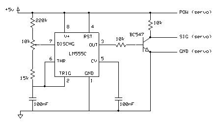
Free Schematic Diagram: Simple servo controller Schematic

Servo-valve module:

Servo-Valve Module

Block diagram of two-stage servo valve with mechanical feedback

Servomechanism (Tracking Mechanism) - Hydraulic Schematic Troubleshooting

a). Principal schematic of servo control valve. | Download Scientific